


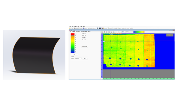
Single-curvature variable-thickness laminate
Carbon fiber laminate
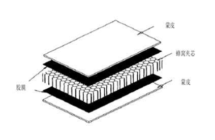
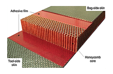
Carbon fiber honeycomb panel
Carbon fiber foam panel
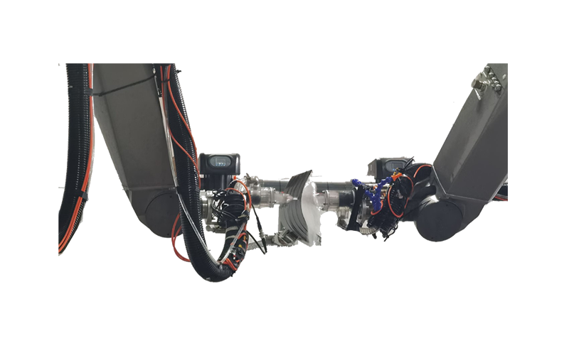
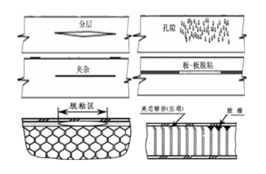
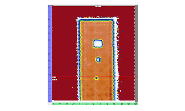
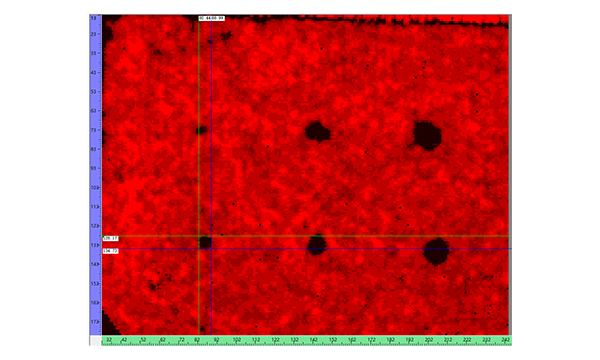
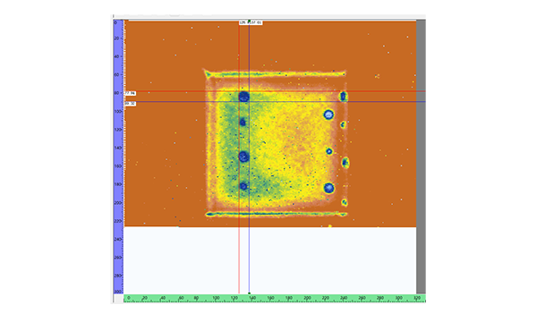
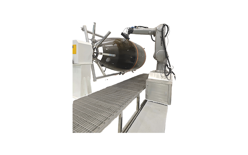
Robot water-jet through-transmission inspection system is independently developed and integrated by Beijing HuaTai KERN Science & Technology Co., Ltd., and manufactured in accordance with the ISO9001 quality system. It adopts a unique dual-robot collaborative architecture, enabling both through-transmission and pulse-echo inspection methods. Designed specifically for composite laminates, bonded structures, and large-size honeycomb sandwich components, the system can inspect laminates with thicknesses from 1 to 40 mm, bonded assemblies from 1 to 40 mm, laminate in core-bonded structures from 0.5 to 5 mm, and honeycomb core heights from 3 to 200 mm. Equipped with interchangeable nozzles and splash protection devices, it is suitable for online inspection of highly curved panels.
ntroduction to the Ultrasonic Water-Jet Through-Transmission Robotic Guide Rail:
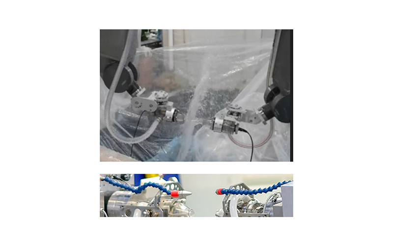
Nozzle
The injector housing is fixed to the robot end effector and protected by a collision protection device. The nozzle housing incorporates a water flow stabilizer to minimize turbulence inside the housing. The detachable nozzle is available with orifice diameters of 6 mm, 8 mm, and 10 mm.
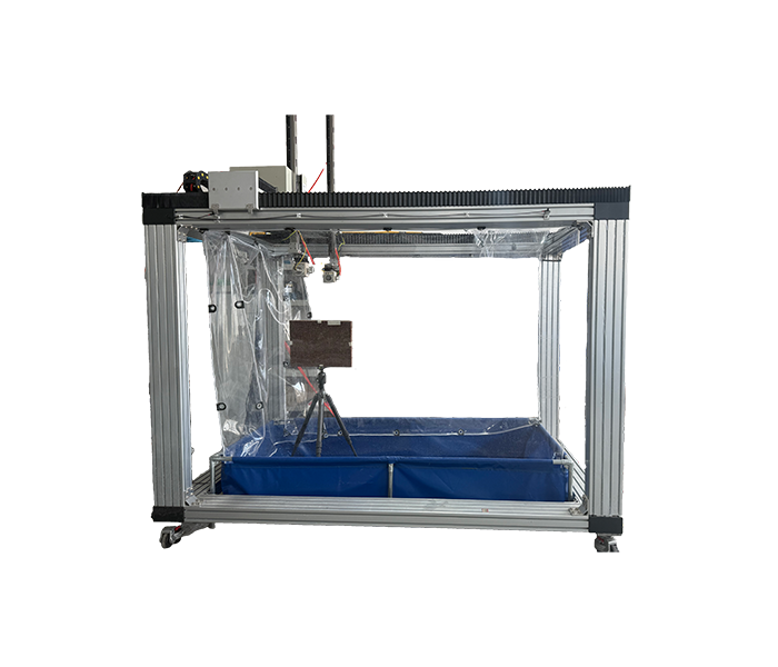
→ The mechanical scanning system operates smoothly, is continuously adjustable, offers good scanning repeatability, and provides consistent accuracy in the displayed inspection images. All electrical control systems used for operation do not cause interference with ultrasonic signal acquisition or adversely affect the inspection results.
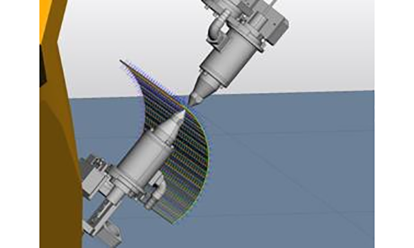
→ Equipped with automatic probe angle alignment and centering function: when using the through‑transmission method, the inspection system performs automatic multi‑axis coordinated scanning according to commands. Over any position within the defined scan range (for complex curved surfaces), it ensures that the acoustic beams of the two probes remain on the same axis, which is perpendicular to the tangential plane of the surface (or parallel to the surface normal). The maximum variation in ultrasonic signal amplitude caused by axis misalignment shall not exceed ±2 dB (under no‑load condition).
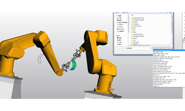
→ The system is capable of multi‑axis coordinated motion control in different degrees of freedom, providing multi‑axis scanning functionality. It can be operated in dual‑robot through‑transmission mode, single‑robot pulse‑echo mode, or single‑robot phased array inspection mode.
→ Capable of inspecting complex curved surfaces, conical parts, and variable‑thickness cross‑sections, while ensuring that the probe nozzles automatically track the curvature of the component surface during scanning to maintain a constant sound path, thereby enabling tracking inspection of variable‑thickness components.
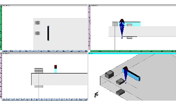
Phased Array Focusing Simulation
3D Coverage Indication of Inspection Range
The system provides fast scan trajectory generation for various part geometries
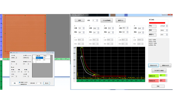
TCG or DAC Curve Plotting
| Phased Array Channels | 128 channels (256 channels optional) | Bandwidth (-3 dB) | 500 kHz to 18 MHz |
| PA Excitation Mode Conventional UT Channels | Max. 32 contiguous elements Max. 2 groups of 16 contiguous elements 2 channels (pulse-echo or pitch-catch configuration) | Amplitude Resolution Load | 16bits 5kg |
| Pulse Width Max. Number of Focusing Laws | 25 ns to 500 ns 1,024 | Working Range Repeat Positioning Accuracy | 900 mm (other ranges optional) 0.025 mm |
| Pulse Repetition Frequency Max. Number of Sampling Points | 20 kHz 16,384 | Software Features | Beam Simulation 3D Workpiece |
| Data Transfer Speed Max. Data File Size | Max. 30 MB/s 20 GB | UltraVision 3 SDK | C#, C++/CLI, or VB .Net supports multi-language programming |
 EN
EN