


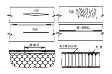
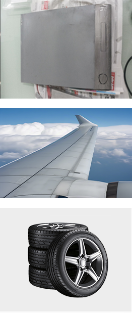
· Debonding
· Delamination
· Cracks
· Dents
· Repair failure defects
· Wrinkles, ripples
· Inclusions:
· Air, water, foil layers
· Foreign Object Debris (FOD)
· Debonding
· Delamination
· Cracks
· Dents
· Repair failure defects
· Wrinkles, ripples
· Inclusions:
· Air, water, foil layers
· Foreign Object Debris (FOD)
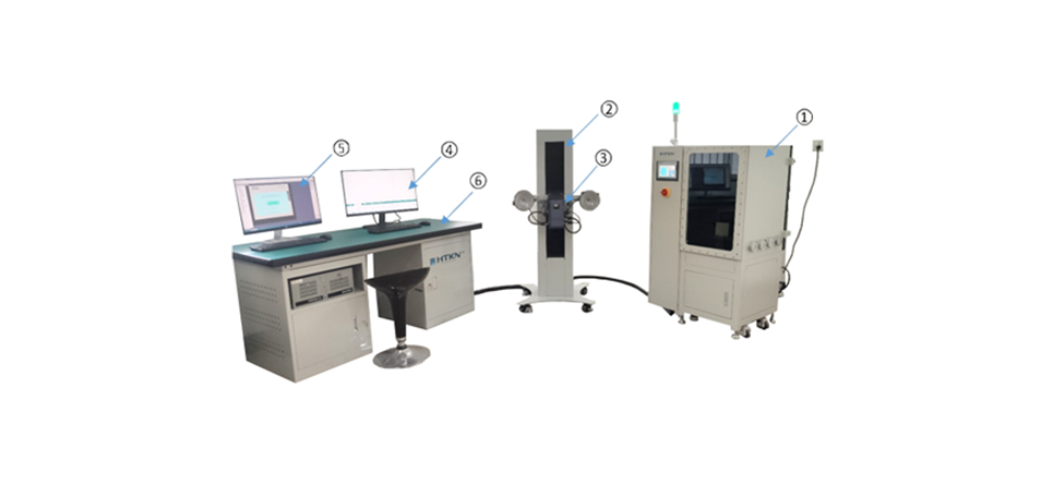
The HT7300 Laser Shearography Testing System consists of:
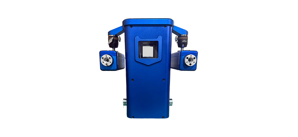
The HT7300 laser shearography instrument adopts an integrated packaging technology for all major components. The instrument internally integrates a CCD camera zoom lens, a shearing device, a phase shifter, etc. The instrument features a high degree of integration, compact size, light weight, and good sealing, making it more suitable for use in factory environments.
The focusing, zoom, exposure, and shearing amount adjustment of the laser shearography camera can be integrally controlled via the testing software. The laser shearography instrument has communication capabilities, allowing data exchange and signal transmission with the vacuum chamber and automatic loading/unloading systems.
| Parameter Name | Value |
| Camera Resolution | 5.01 megapixels |
| Zoom Lens | 12 mm - 36 mm (customizable) |
| Laser Power | 400 mW (customizable) |
| Laser Wavelength | 532 nm (customizable) |
| Max. Inspection Area per Scan | 800 × 600 (customizable) |
| Shear Direction | 0-360° |
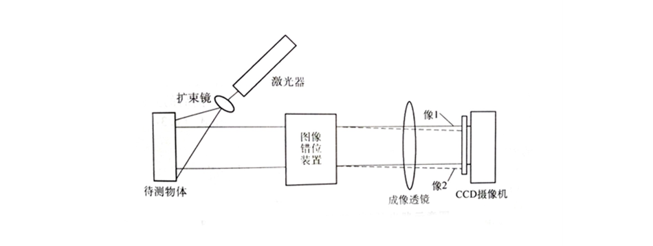
Shearography is a common-path, self-referencing interferometric measurement method. The laser beam is split by an optical shearing device, and passes through optical lenses to form two mutually sheared images of the object on the photosensitive surface of a CCD. The two sheared images interfere with each other, generating a speckle pattern determined by the surface topography of the object. This speckle pattern changes with the deformation of the object surface.
Laser shearography offers advantages such as non-contact operation, no contamination, no limitation by workpiece geometry or size, high inspection sensitivity, and high inspection efficiency. Its essence is to measure the micro-deformation (i.e., out-of-plane displacement) of a defect area on the surface under load.
The laser shearography instrument lifting mechanism consists of a linear screw, guide rails and a sliding table, an electric pan-tilt unit, a servo motor, etc. It is mainly used for vertical movement of the laser shearography instrument along the Z-axis. The lifting mechanism, together with the vacuum chamber turntable, enables 360° full-coverage inspection of the product. The lifting mechanism supports both automatic and manual lifting according to process parameters. The pan-tilt unit provides functions such as horizontal rotation and pitch angle adjustment.
| Parameter Name | Value |
| Lifting Mechanism Dimensions | Customized |
| Z-axis Effective Stroke | Customized |
| Pan-tilt Vertical Tilt Angle | 45° |
| Pan-tilt Horizontal Rotation Angle | 90° |
| Servo Motor Explosion-proof Rating | Exd IICT4 |
| Lifting Mechanism Mounting Metho | Leveling feet and mobile Fuma casters |
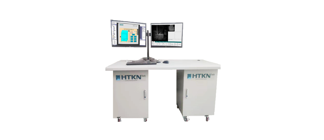
The control console is a standard industrial-grade console, incorporating a desktop workstation and displays for the operation and visualization of the shearography inspection software and mechanical motion control software. The computer provided by our company is a Lenovo workstation-grade unit, equipped with an i7 processor, 16 GB RAM, 2 TB HDD, 500 GB SSD, a DVD-RW drive, and runs the Windows 10 operating system. The monitors are 4K LCD displays: Lenovo brand, quantity 2 units, screen size 24″, resolution 3840×2160.
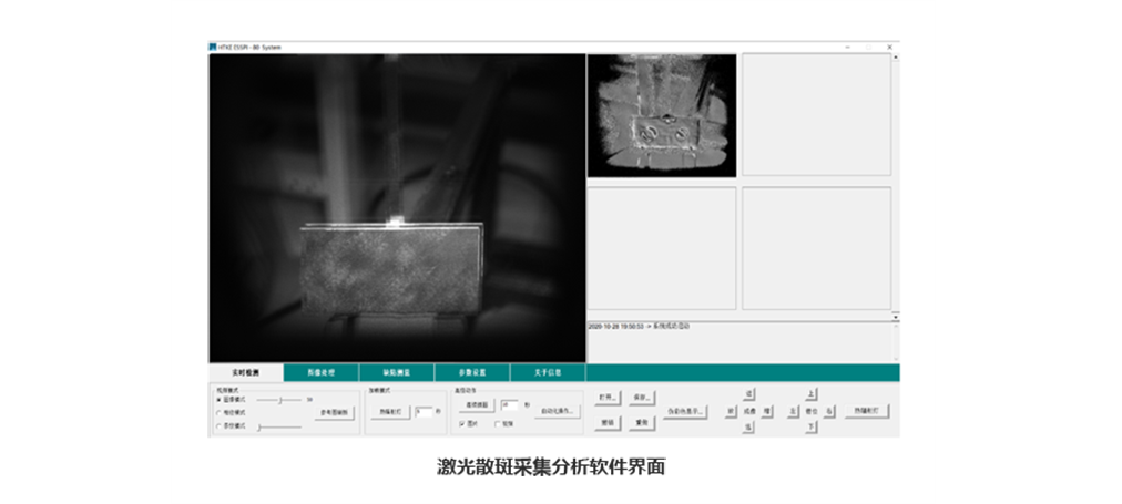
The laser shearography analysis software developed by our company features a Chinese user interface with good human-computer interaction. The inspection software can be installed on Windows 7 or Windows 10 operating systems. The operation is simple and flexible, allowing it to arrange complete measurement and evaluation tasks.
The software can control CCD camera image acquisition, shearing amount adjustment, lens focusing and zooming, and can achieve functions such as image acquisition, processing, automatic defect identification and measurement, and automatic storage of inspection images. Using the latest software engineering technologies and standards, it enables both manual and automated inspections.
· Full-field inspection, real-time imaging, high inspection efficiency;
· Phase-shifting technology greatly improves inspection image quality and sensitivity, achieving nanometer-level displacement measurement sensitivity;
· Non-contact inspection, low requirements on object shape and surface finish;
· Digital images, easy to record, process, and transmit;
· Intuitive image-based inspection results;
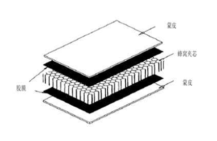
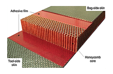
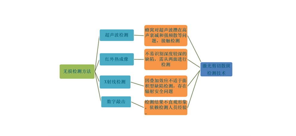
· Suitable for detecting defects such as delamination and debonding in composite laminates and honeycomb structures.
 EN
EN